Open Section U: Quality Assurance Devices, GARD, ISIS, Couch Cubes(PDF) to view related products. (Opens in a new tab)
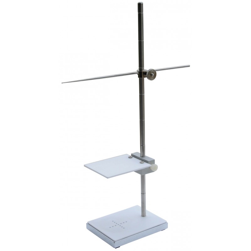
Optical Distance Verification & Alignment Tool, with Isocentric Ball Pointer.
This system will calibrate optical distance indicators on accelerators, cobalt units and simulators. The ball pointer is used to determine the rotational Isocenter of the treatment machine collimator head and gantry. The ball pointer is also visible in fluoroscopy on simulators.
Instructions
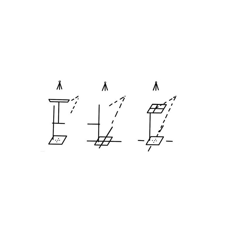
Step 1
Determine the most useful range (40 cm or less) of the Optical Distance Indicator (i.e. 80 cm to 120 cm range with a 100 cm Isocenter). Figure 1 - set the white plastic tray five steps (20 cm) down from the top. Use an Accurate Mechanical Distance Rod adjusted for 100 cm Isocenter and adjust the couch height until the distance rod just touches the white plastic tray.
Step 2
Figure 2 - rotate the white plastic tray around 180o out of the field and adjust the alignment tool so crosshairs align with the black dots on the base plate.
Step 3
Figure 3 - raise the white plastic tray up 20 cm. This tray would show field light crosshairs intersecting with 80 cm. The black dots on the base represent the crosshairs and will intersect with 120 cm.
Step 4
Adjust the Optical Distance Indicator so that 80 cm and 120 cm are obtained at the same time. When both points are precisely on, linearity can be checked in 5 cm steps by moving the plastic tray down the rod.
Specifications
Optical Distances: 5 cm steps to 40 cm
Material: White plastic w/mat finish and black dots
Ball Pointer: 1/16” dia. ball on 12” long rod
Rod Clamp
Base: 10 cm W x 13 cm L x 1/2” T zinc plated steel w/rubber feet
Height: 43 cm
Weight: 4 lbs